We use GPIO to talk to external devices on the NVIDIA Jetson Nano. Looky here:
Introduction
One of the nice things about the Jetson Nano is that there is an expansion header which is useful for General Purpose Input Output (GPIO). You may have thought about turning a light on or off as the output of your program, or would like a read a press from an external button. That’s where GPIO is useful!
In this article, we’ll cover how to control GPIO output by turning a Light Emitting Diode (LED) on and off. This is probably one of the most basic examples on how to use GPIO.
As you may have heard, the GPIO pin layout on the Jetson Nano is compatible with the 40 pin layout of a Raspberry Pi (RPi). Also, there is a Jetson GPIO python library which is mostly compatible with RPi.GPIO. Jetson.GPIO is preinstalled in the standard Jetson Nano disk image.
With that said, note that the electrical characteristics of the GPIO expansion header on the Jetson Nano are not the same as a Raspberry Pi. In particular, the Jetson Nano flows much less current on the GPIO pins than the RPi.
For example, a RPi can drive a LED directly from the GPIO pins, whereas a Jetson leaves the LED dimly lit because there is not enough current. The Jetson needs a little help. As you will see, a switching transistor comes to the rescue!
There are a couple of ways to use this article. The first way is to work your way through everything, and use your pearl catcher to grab the wisdom being thrown about. If you’re more pragmatic, jump around to the bits and pieces you find useful. Be forewarned that there be maths here, we’re using electricity, and things could go horribly wrong if you’re not careful. Other than that, play and have some fun.
LED Circuit
Parts List
Here are the parts we are going to use in this circuit:
- A 5mm red LED
- A P2N2222 Transistor
- 1 330Ω resistor
- 1 10kΩ resistor
- Hookup wire
- A breadboard to connect everything together
The easiest way to acquire the parts is to get a collection, such as this “Electronic Fun Kit“. There are many of these types of kits available for experimenting with Raspberry Pi and Arduinos. You may also want to acquire some extra resistors or such. Sparkfun and Adafruit are good sources.
It is also useful to have a multimeter on hand. I use a pretty hard core one, but if you’re just starting out you can get a less expensive one instead.
LEDs
If you want a little more in depth introduction to LEDs, checkout “A detailed introduction on how to use LEDs” This should give you a good feel for what we are doing here.
Here’s the thing about LEDs. They don’t use power linearly. Like little pigs they’ll suck so much current up that they will destroy themselves in a puff of magic smoke if left to their own devices. But we can make sure that does not happen.
By adding a resistor (in this application it is called a current limiting resistor), we will limit the amount of current that the LED is able draw. We select the resistor based on Ohm’s Law.
Oh My! Maths …
One of the fundamental rules in electronics is Ohm’s law. You have probably heard about it. Specifically:
Ohm’s law states that the current through a conductor between two points is directly proportional to the voltage across the two points. Introducing the constant of proportionality, the resistance,[1] one arrives at the usual mathematical equation that describes this relationship:[2]

where I is the current through the conductor in units of amperes, V is the voltage measured across the conductor in units of volts, and R is the resistance of the conductor in units of ohms. The main point to remember is that current, voltage and resistance are all related.
And what does that mean to us? In short, we can set the limit on the amount of current that the LED can actually draw by cleverly selecting a proper resistor. This is because a resistor’s current value responds directly proportional to the applied voltage. All we need to know is a couple of things about the LED to calculate the proper resistor value.
First, LEDs have what is called a Forward Voltage, which is basically the minimum voltage difference between the cathode and anode (different terms for this is the minus and plus sides) that you need to supply to an LED. Another thing that we need for our calculation is the Forward Current which is the maximum amount of current that the LED is able to handle continously.
In the LED data sheets, you will see Forward Voltage as $V_F$ and Forward Current as $I_F$.
The LED in this example has a Forward Current of 20mA and a Forward Voltage of 2.0V. We will be using the Jetson Nano 5V pin to drive the LED, so we subtract the Forward Voltage from the 5V and divide by 20mA (0.020A), just like Ohm’s Law tell us to:

We get a result of 150Ω This is the value to flow the maximum amount of current that is safe for this particular LED. A couple of things to note here. First, resistors don’t tend to come in a 150Ω flavor. Even if they did, they have some tolerance built in, which indicates they can have some variance from the actual stated resistance. This is usually a small percentage, but smaller inexpensive resistors may be around 20%! This means that the resistor can be in a range of 120-180Ω for one rated at 150Ω. Because we live in a modern age, we can use an online calculator to help us for this calculation.
Second:
Tyrell:
Blade Runner, 1982
The light that burns twice as bright burns half as long – and you have burned so very, very brightly, Roy.
Maybe not quite as drastically as the movie quote, but running an LED at maximum current will effect its lifespan. Typically people end up using between 220 and 470Ω resistors for this application. We will be using a generic 330Ω.
About that Transistor
That takes care of protecting our little LED friend. But as we were talking about, because a Jetson Nano GPIO pin is not strong enough to power the LED by itself it needs a little help. We will use a Transistor which will act as a switch to provide current to the LED.
Transistors amplify power. We will be using a Bipolar Junction Transistor (BJT). BJTs are available in two flavors, PNP and NPN. We will be using a NPN transistor, which is what the majority of low power switching circuits use. If you want a deeper background see: A practical guide to transistors and their use. A BJT is made up of three pieces of silicon. A NPN transistor has a piece of P-Type silicon (the Base) sandwiched between two pieces of N-Type silicon (the Collector and the Emitter).
Fun Fact: If you don’t know what P-Type and N-Type mean, here’s a quick explanation. A silicon crystal by itself is an insulator. Adding a minute amount of impurities turn the silicon from a good insulator to a viable (but not great) conductor (hence the name semiconductor). A process called Doping introduces impurities into the pure silicon crystal in order to modify the conductivity. Typically Boron (P-Doping) and Phosphorus (N-Doping) are used. Combining P-Type and N-Type silicon allows electricity to flow.
We are making the most fundamental transistor switch circuit. A normal switch would require a mechanical device to physically flip the circuit. Our switch here will be controlled by the current sent from the Jetson GPIO pin to the transistor. The control signal from the Jetson flows into the Base of the transistor, the Emitter connects to ground, and the output is tied to the Collector.
The Circuit
Here’s a schematic of the circuit we will be using:
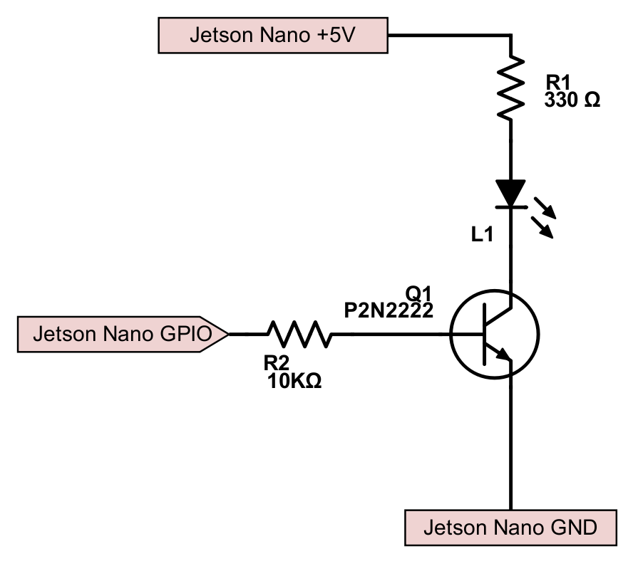
- L1 is our 5V LED
- R1 is the current limiting resistor for the LED
- Q1 is the transistor we’ve been talking about, a P2N2222
- R2 is the Base Resistor which tells how much current to let flow in the circuit.
- For this circuit, use a NPN BJT transistor
Calculating the Transistor Bit
There’s one more bit of mystery. When the Jetson GPIO is low (0V), the transistor is in cutoff mode. It looks like an open circuit between the Collector and the Emitter.
However, there is amount of current applied to the Base at which point the transistor starts to “saturate”. This then acts like a short circuit between the Collector and the Emitter. At that point, current flows and our LED lights up, all nice and happy.
In our example the Base current is determined by a Base Resistor which sits between the Jetson GPIO pin and the base of the transistor. The Base Resistor performs much the same function as the current limiting resistor on the LED. Note that the saturation of the transistor is determined by current, not voltage in a BJT.
There’s a little more math involved to figure out what value the Base Resistor should be.

This reads as the current on the Base of the transistor is equal to the desired current at the Collector divided by the gain of the transistor. You remember that transistors are amplifiers, and have an associated gain. The term hFE in the transistor data sheet is the gain number. For this particular transistor, it is equal to 100. If we provide 0.00020A to the Base of the transistor, we should get 20mA at the Collector.
There’s one more little trick. We need to use Ohm’s Law one more time. We know that the GPIO of the Jetson is 3.3V. We divide that by the 0.00020A to get the Resistance, right? Nope. It turns out that there is a 0.7V drop between the Base and the Emitter that we need to take into account. This drop is attributable to the N-P junction of the Base to the Emitter in the transistor. So:
In this circuit, the 13000Ω value of the Base resistor is the maximum resistance that you can have to get 20mA at the Collector.
You will notice that in our circuit we threw in a 10kΩ resistor instead of the 13kΩ. This is for a couple of reasons. First, we know that the LED won’t draw more than 20mA because of the limiting resistor from earlier. Second, 13kΩ is not a common resistor value, so we need to substitute. If you want to be safe, you would tend to go up a size rather than down. But we live wild! And we have a fire extinguisher.
There are also transistor calculators online if you need to check your maths.
Wiring
We’re now ready to wire everything up and give it a spin. Both LEDs and Transistors flow current in only one direction, and have a + and – side. For the LED, + is the anode, – is the cathode. On a 5mm LED, the + side usually has a longer leg, and usually the – side has a flat spot on the rim of the bulb.
For the Transistor, the Collector goes to the + side, and the Emitter goes to the – side. The arrangement of the pins depends on the particular part chosen.
Given the schematic above, here’s a wiring diagram:

You will need to examine your transistor. The Collector, Base, and Emitter are different depending on which part number you have. We’re using a P2N2222 here. We will be wiring the red wire to +5V on Pin 2 on the Jetson, the black wire to GND on pin 6, and the transistor Base through the base resistor on Pin 12. Pin 12 is selected for the demo examples below.

Software
Once everything is wired up, we’re ready to run some software to blink our light.
We can control our LED from the command line. Here are some useful commands:
# Map GPIO Pin

# gpio79 is pin 12 on the Jetson Nano

$ echo 79 > /sys/class/gpio/export

# Set Direction

$ echo out > /sys/class/gpio/gpio79/direction

# Bit Bangin'!

$ echo 1 > /sys/class/gpio/gpio79/value

$ echo 0 > /sys/class/gpio/gpio79/value

# Unmap GPIO Pin

$ echo 79 > /sys/class/gpio/unexport

# Query Status

$ cat /sys/kernel/debug/gpio
In the above code, the 79 refers to a translation of the Linux sysfs GPIO named gpio79. If we look at the Jetson Nano J41 Header Pinout, we can see that gpio79 is physically pin 12 of the header.
Note: Except for the power, ground, I2C and UART pins, the header pins are GPIO in the Jetson default configuration. Any extra names in the Header Pinout refer to preferred usage if the user makes changes to the device tree and reassigns the pins.
In order to be able to access the GPIO pins, you need to have the proper permissions. This can be accomplished in a couple of ways. First, you can run your commands from a super user terminal. Open the Terminal and execute:
$ sudo su
2-15-2020 This section was originally written for releases before JetPack 4.3. For JetPack 4.3, the udev rules are in: /lib/udev/rulesd/60-jetson-gpio-common.rules
This should mean that you don’t have to copy the file anymore with JetPack 4.3 and above. Also, it appears as if the default is for users to be included in the gpio group. You can check this by:
$ groupsYou are then able to execute the commands with the correct permissions. Also, the permissions can be assigned to a group which you are a member. This is typically done by:
$ sudo groupadd -f -r gpio

$ sudo usermod -a -G gpio your_user_name
Install custom udev rules by copying the 99-gpio.rules file into the rules.d directory:
$ sudo cp /opt/nvidia/jetson-gpio/etc/99-gpio.rules /etc/udev/rules.d/
Please note that for the new rule to take place, you may either need to reboot or reload the udev rules by issuing this command:
sudo udevadm control --reload-rules && sudo udevadm trigger
This sequence is from the Jetson-GPIO Python library documentation, which is installed in the default Jetson Nano image at: /opt/nvidia/jetson-gpio/doc/README.txt.
Jetson.GPIO Python Library
There is an official Jetson.GPIO library for Python. The Jetson.GPIO library aims to be compatible with RPi.GPIO.
2-15-2020 For JetPack 4.3 and above, the samples are now in: /usr/share/doc/jetson-gpio-common/samples. In previous JetPack versions, they were in: /opt/nvidia/jetson-gpio/samples
We can run the sample for simple output to control our LED:
$ cd  /usr/share/doc/jetson-gpio-common/samples

$ sudo ./run_sample.sh simple_out.py
The run_sample.sh script sets up the paths to the Jetson.GPIO library and calls simple_out.py to flash the LED that is connected to pin 12 on the GPIO header.
This is just touching the Jetson.GPIO library, it is much richer than just this. We’ll examine more functions in subsequent articles.
Conclusion
While it seems like a lot to know to turn LEDs on and off, we now have the foundation to control external devices over the Jetson GPIO Header. In our next installment of the GPIO series, we’ll take a look at input through the GPIO header. Stay tuned!
Notes
Here’s some useful information from the NVIDIA Jetson Nano Forum. PinballWizard writes:
The Jetson Nano carrier board uses TXB0108 bidirectional voltage-level translators on the GPIOs to go from the module’s 1.8 V levels to the headers 3.3 V levels. The data sheet for the TXB0108 states “With regard to capacitive loads, TXB translators are designed to drive up to 70 pF without issue.” The capacitance of my test leads is above 70 pF, so I tried an oscilloscope with 10 MΩ, 16 pF probes and the Jetson Nano outputs work fine. With both the multimeter and oscilloscope connected, I get a 56 MHz oscillation on the outputs. The multimeter reads the average, which is ~1.55 V.
The TXB0108 also has a 4 kΩ output impedance. That combined with the 70 pF capacitance limit means that any load on the Jetson Nano’s GPIOs should be both high impedance and low capacitance.
61 Responses
Great work! Can you tell me what is the maximum current that each pin can supply and maximum total current from all pins ?
The exact numbers have not been published yet, they should be out in a couple of weeks. For the Jetson TX1 and TX2, I2C pins are 1mA/-1mA, UART pins are 24mA/-24mA, and other pins range from 20uA/-20uA to 1mA/-1mA Note that it is 20 micro Amps. I expect that the Jetson Nano is similar, but won’t know for a while. Thanks for reading!
Jetson Nano is like a very good student with a big brain, but in sports needs help lol.
Thank you for the reply
you know, TXB0108 DS says like IO Continuous output current is ±50 mA.
hmm…
http://www.ti.com/lit/ds/symlink/txb0108.pdf
I don’t know what this means.
@Andrey Taranov So that means that I can connect an Optocoupler out of the TXB0108 ? For example the 4N32 The datasheet says that Forward current is 60mA, I’m not sure if that will work or I need an extra transistor to power up the 4N32
Regards
Jose
Your videos are great! They are providing us with a lifeline to making this Nano thing work in reality. We will be attempting to use the Nano to control a heap of servo motors via Adafruit’s 16-Channel 12-bit PWM/Servo Shield with its I2C interface, so if you just so happen to use that as an example in your I2C video, we promise not to become so ecstatic it kills us. Thanks!
Thank you for the kind words. That’s an awful big promise to make too.
How are you using your PCA9685 interface?
OMG! Just a few days ago my students were on the verge of tears trying to get their Nano to run some servo motors via the i2c link when, lo and behold, they found your video using Adafruit’s 16-Channel 12-bit PWM/Servo I2C thingy! They got their system working now. You saved the day – maybe even their summer. You’re like a saint or something. I promised we wouldn’t become so ecstatic that it kills us, but we sure have come close to it. Thank you! Thank you!
On the verge of tears? Most people have that reaction *after* they watch my videos! Or at least the ones that are still awake afterwards.
I’m glad they got it to work, tell them I said “Hi”.
Hi! Did this work? I have a rpi servo hat I want to use on the nano.
Check out his video using the i2c. I don’t think his website has a link to it yet.
Just be aware when you’re using shields or hats, etc. that there is some power wiring, etc. that comes up to those shields or hats from the boards they are usually attached to, and so that won’t be provided by the Nano unless you wire it directly.
https://www.youtube.com/watch?v=RnGUTny1hG8
Hi Kangalow,
we’re attempting to “embody” an AI and have it learn with that physical body (rather than just crunch through sets of disembodied data). Our hope is that we can get a Nano to learn to track the movement of an object and have a simple robot (on a chassis with wheels driven by servos) follow that object around in 3-D space. Our first step aims to have the robot track an object back and forth with the same kind of behavior one might expect from a robotic system controlled by a classic PID loop but have it learn on its own. So maybe a “heap” of motors was an exaggeration, but we’re certainly going to need at least 3 if this starts to work. Thanks!
I’m using this with a 5v relay switch. Noticing that the echo 1 and 0 have no effect on the switch while switching in to out turns the switch on and off. What exactly are low and high supposed to do vs. in and out? And risks to using in as the switch mechanism?
I don’t understand your description. Typically you would give a code snippet or something to put a context around how you are using these commands. Also, it is difficult to understand how you are using the 5V relay switch without some type of description of the wiring diagram, and a description of the part. The GPIO pins on the Jetson are 3.3V. Does the relay use a 5V signal, switch on a 5V signal, or something else?
Here’s the description for you. The switch has 3 input/outputs on either side. One side had NO, COM and NC. The other has VCC, GND and IN. I’m also using a barrel jack to plug the power supply in
NO gets the positive side of the barrel jack, COM gets the positive side of the LED wire. GND gets a GND pin on the nano, VCC gets the 3.3v pin and IN gets the GPIO pin 79. Using the in/out commands I can turn on/off the switch. The Hi/Lo commands have no effect.
It’s been working fine using the 3.3V input, however the nano only has 2 3.3V inputs. So I tried the 5V. That also turns on the switch, but I can’t get it to turn off the switch. Both with using the In/Out and Hi/Lo commands.
Question for you. What do you think In/Out do? Also, what do you believe the Hi/Lo commands are? Do you have a part number for the relay?
What is the code you are using?
Great Blog as usual
Just a little typo here: sudo ./run_samples.sh simple_out.py
should be sample with no “s”
Good catch! Fixed the text. I appreciate you taking the time to report this, and thanks for reading!
Great tutorial, thank you!
I’m looking to interface the Nano’s GPIO with C++ library instead of python, so I can reuse existing code. Have you stumbled upon a good solution?
Thank you very much for your blog posts!
-Phil
Thank you for the kind words. The recommended GPIO interface is libgpiod:
https://github.com/brgl/libgpiod
Thanks for reading!
Thanks for the great article as usual!
I was trying to figure out what this business with mode BCM vs mode BOARD means. From the documentation:
“`
… uses the BCM pin numbering mode from
Raspberry Pi and outputs alternating high and low values at BCM pin 18 (or
board pin 12 on the header) …
“`
At first I didn’t understand this because the raspberry pi pin numbering is the same as the nano J41, but after looking at the pi
pinouts I realized that in BCM mode the channel number is the *gpio* number (in this case gpio18). This number does not
match the gpio number on the nano however.
In summary, to use nano gpio79 you either use BCM18 or BOARD12 (pi gpio 18 or pin number 12).
Yes, it’s a little confusing. Bringing the legacy BCM numbering makes it about as clear as mud. Thanks for reading!
Hi Sir,
i am trying to access gpio pins in jetson nano development kit ,i would like to perform i2c , spi and uart applications in jetson nano using c program but i couldnt find any tutorial or documents what i am looking for,i could only able to find examples in python version, please guide me and please share the needful documents and tutorial links to access gpio in jetson nano in c version.
As noted in the I2C article, you can use libi2c (https://github.com/amaork/libi2c) to access I2C for C/C++ and Python. For GPIO, you can use libgpiod, which is part of the kernel. Good luck on your project!
Actually Jetson works in two power modes i.e., LOW and HIGH. To set Jetson in low power mode type the following command-
$ sudo nvpmodel -m1
$ sudo nvpmodel -q
As you enter these commands your Jetson will start working in LOW Power mode and now you can easily control the GPIOs
This is not related to GPIO. nvpmodel controls the power consumption of the Jetson by setting the clock speeds of the CPU and GPU. The Jetson Nano has a 5W and a 10W mode through nvpmodel, which represents the amount of current draw for the configuration CPU/GPU clocks.
Can I know input impedance of a GPIO pin in jetson nano or jetson TX2
I don’t know what this means. Please ask this question on the official NVIDIA Jetson forum where a large number of developers and NVIDIA engineers share their experience. The forum is here: https://devtalk.nvidia.com/default/board/371/jetson-nano/
Kangalow,
I have not had much luck getting a response from you in other posts, but here goes another try.
What do you think is needed to access the GPIO in ROS?
I have an Adafruit Motorshield v2 and it appears to use 5V I2C so I would love to create a package that can activate a couple of TT Motors directly without the use of ROS-Serial. Any thoughts?
Cheers,
Coach
I don’t know what other questions you have asked. To be clear, I get dozens of questions a day and I certainly don’t have that many answers in me. If I don’t have anything to share about a particular questions, I leave it in case others have some experience and can help answer.
Your question is difficult to answer. I don’t have any experience with the device you mention. There’s a whole article on how to use I2C on the Nano: https://jetsonhacks.com/2019/07/22/jetson-nano-using-i2c/ It’s not clear why you would have a ROS system and not use ROS to drive motors. It’s not clear why you would use the GPIO package to use I2C.
A glance at the tutorial: https://learn.adafruit.com/adafruit-motor-shield-v2-for-arduino?view=all&gclid=CjwKCAiA6vXwBRBKEiwAYE7iS_BEchFI_3Z3M0gaf-9V3kInuuueZKGPJ1VttfB1eg7TNXNmTifxbRoCRW8QAvD_BwE mentions that the logic is 3.3V compatible with a jumper, and you need 5V to power the motors:
Quote:
For use with the Due or other 3.3v processors, you must configure the board for 3.3v logic levels. Find the set of 3 pads labeled “Logic”. Cut the small trace between the center pad and 5v and add a jumper from 3.3v to the center.
So, I’m not sure what your question might be, it sounds like you already know what you are trying to do. Good luck on your project!
Kangalow,
To clarify, I have posted on the article about Intel Realsense and the TX2. I can’t seem to find the article now. But anyway, thank for the GitHub Repo in which you make installing the SDK for Realsense. It built it on the first try. I am getting an error however during launch. I can’t recall what it was now. Your repos really do help! So thanks for those.
“It’s not clear why you would have a ROS system and not use ROS to drive motors. It’s not clear why you would use the GPIO package to use I2C.”
Maybe I am not understanding this clearly. In my mind, I need to write a ROS package that would communicate directly via I2C to the motorshield and not use ros-serial to talk to an Arduino to drive the motors. I would like to build my own spin on the NVidia Jetbot.
Their example uses machine learning to drive the same TT Motors I have but with a different motorshield for the Feather footprint. And like NASCAR, it only does left turns. I would like to create a two wheeled rover that has an RPLIDAR S1 for some SLAM mapping.
I don’t quite know as much as I might have projected and for that, I apologize. I was thinking that there might be a method like:
#include /jetson/gpio.h
In a ROS package that I can call so when using Teleop-Keyboard; so when a linear velocity is published in cmd_vel, the package would interpret that and send a message via I2C to the Adafruit Motorshield to cause forward movement (or whatever movement is needed to match to the end goal).
In terms of power, my thoughts were to use a power bank with a couple of outputs and feed the 5V to the Nano as required and take a second port to power the Motorshield with its own power. Doing so, might cut down on mulitple battery packs and keep the overall wiring and appearance clean.
I was not aware of the 3.3V logic on the Nano. I assumed it was 5V so thanks for clearing that up. The motorshield is capable of being powered separate. So if my thoughts are straight on this, I can jump to the 3.3V logic while still providing that shield with ~5V and only use the GND, SDA and SCL.
Am I thinking correctly on this? Or have I still missed your talking points? Again I am very thankful for what you provide and know you get pinged quite a bit with questions. I hope my typing tone didn’t come off harsh. It’s just that the commenting system and finding my previous comments on the article is confusing. The only way for me to get updates is to keep this tab open and refresh the page.
Cheers,
Coach
I believe your outline is correct. See this: https://github.com/dusty-nv/jetbot_ros/blob/master/scripts/jetbot_motors.py
However, I don’t understand how you would use gpio.h in the scenario you describe. I would think something more along the lines of: https://github.com/adafruit/Adafruit_CircuitPython_MotorKit would be appropriate.
Good luck on your project!
Hi Jim,
I believe JetPack3.4 moved things around.
cp: cannot stat ‘/opt/nvidia/jetson-gpio/etc/99-gpio.rules’: No such file or directory
Thanks, I’ll look into it.
Jim, did you have a chance to take at look at
sudo cp /opt/nvidia/jetson-gpio/etc/99-gpio.rules /etc/udev/rules.d/
cp: cannot stat ‘/opt/nvidia/jetson-gpio/etc/99-gpio.rules’: No such file or directory
Hi Jack,
I believe that starting with JetPack 4.3 the rules are now in:
/lib/udev/rulesd/60-jetson-gpio-common.rules
Which means that you should not have to do anything to get them to work, as /lib/udev/rules.d is one of the default paths the system looks for. I changed the article to reflect this. However the new read doesn’t quite flow as well as I like. Thanks for finding this!
Roger that. Thank you!
Keep up the good work
Jack
Hi Jim, Have you tried running a micro servo from GPIO33 as per the /jetson-gpio/samples/simple_pwm.py example?
we got as far as adjusting the pinmux and got lost?
https://docs.nvidia.com/jetson/archives/l4t-archived/l4t-281/index.html#page/Tegra%20Linux%20Driver%20Package%20Development%20Guide/l4t_pinmux.html
I have not tried them. You should ask for help on the Jetson Nano forum and see if others have any experience to share.
Just been looking at this. With Jetpack 4.4 I now see the voltage as 4.5v open circuit on the GPIO outputs. Are you sure it is 3.3v?
It is difficult to tell from your description which pins you are measuring, how you are measuring them, or what you mean by “open circuit”. You can look at the schematics for the carrier board if you need more specific information.
I am measuring pin 7 relative to pin 6.
i.e. GPIO 216 relative to ground. I read 0v when low and 4.56v when high.
Weird that the user guide (https://developer.download.nvidia.com/assets/embedded/secure/jetson/Nano/docs/NVIDIA_Jetson_Nano_Developer_Kit_User_Guide.pdf) agrees with you about 3.3v. :-S
Thanks for the tutorial. Really helpful.
You are welcome, and thanks for reading!
I am working on a project where I need multiple LEDs to work with the Jetson Nano and I want to ask if there is a similar way to your description here.
My Idea was I use the other pins like 4, 9 and 16 to control a second LED. Does this work?
Hi there! incredible overview of the Jetson Nano GPIO! would just like to clarify that in the article you mentioned that “the Jetson Nano flows much less current on the GPIO pins than the RPi” may I know what is the current flow from the GPIO pins for the Jetson Nano as well for the RPi as it is not mentioned. Thank you and once again incredible read!
Thank you for the kind words. All of the Jetsons pad drive strength is +/-1mA or +/-2mA at 1.8V or 3.3V depending on how configured. The Raspberry Pi is typically ~ 16mA. Thanks for reading!
kangalow,
Thank you for this very nice and well explained tutorial.
Would this same circuit work with the 1.8v provided directly from the nano module gpio (not the 3.3v after the level translator on the devkit carrier brd)? Thanks!
kangalow,
Would this same circuit work with the 1.8v provided directly from the nano module gpio (not the 3.3v after the level translator on the devkit carrier brd)? Thanks!
Hello Kangalow,
Would this same circuit still apply if it were 1.8v driving the base of that transistor?
thanks
Hello Kangalow,
Please how do I autostart my C program at system startup?
I have tried /etc/rc.local and crontab but my OS didn’t startup because the program was stuck in the while loop in my C code.
Did you try spawning your program into a different thread so it does not block the main one?
I run in the problem with more than 144 Leds controlled by Jetson, has anyone same issue? I’m using adafruit.
We are way past 4.3, I found the samples in usr/share/doc/jetson-gpio-common/samples and ran simple_out.py (after I upgraded python to 3.10) no errors from python, screen is full of Outputting 1 then 0 to pin 18
But no LED changing. This is on my B01 that has a full case so it is hard to see inside. I’ll take a A01 apart and try it.
I need to use SPI for ePaper, is there somewhere that shows setting up SPI and I2C?
Thanks
Here’s an article for SPI: https://jetsonhacks.com/2020/05/04/spi-on-jetson-using-jetson-io/
There are various articles about I2C, you can use the search box to find them on the site. Thanks for reading!
Is the transistor in the photo & breadboard diagram backwards? It looks like the collector and emitter are reversed, and it should be installed the other way.
I believe that it is correct in the article and picture. The transistor is a P2N2222. The P2N2222 swaps the emitter and collector in comparison to a PN2222/2N22222. https://commons.wikimedia.org/wiki/File:2N2222,_PN2222,_and_P2N2222_BJT_Pinout.jpg I believe the implementation matches the circuit schematic. Let me know what you think, and thanks for reading!
Yes, that’s right, I didn’t realize they came in both pinouts. Thanks for the prompt reply, even 4 years after the article was published! This article was just what I needed for a project.
Hardware is always tricky that way, being physical and all that. I’m glad you found the article useful.