Adding a Hokuyo UST-10LX Scanning Range Finder to RACECAR/J is probably the most difficult task in the build to replicate a MIT RACECAR. With a little patience, it’s not too difficult. Looky here:
Background
One popular approach to vehicle autonomy is to add lidar and use the output to map the surrounding environment. On full size cars, 360 degree lidar maps the surrounding environment. In turn, this map goes to the onboard computers which then use the information for path planning, object segmentation, obstacle avoidance and so on.
In order to avoid “blind spots”, supplemental sensors such as additional lidars, radars, and cameras may be in use on the vehicle. There are several challenges with this approach. One of the major challenges is “Sensor fusion”, which means combining all of the information from the sensors in to one overall operating picture.
Another challenge is that the lidars themselves have a couple of things going against them. First, current implementations tend to be rather pricey (a good 3D lidar can cost ~ 75,000 USD). Second, most of the lidars available today are mechanical implementation with spinning mirrors, motors, and other bits to produce the magic.
The magical future promises that once the devices start mass production and the inevitable “solid state revolution” occurs, the price of the devices will drop to an affordable level. As technology folks, we all know the “Future Starts Slow”, and that it might take a while for this to happen.
For the MIT RACECAR, the lidar on this car is at a smaller scale, yet presents some of the same fundamental issues when combining with other onboard sensors. For this application, the lidar is 2D and is in a small package. The Hokuyo UST-10LX has impressive specs:
- Scanning Range: 0.02 to 1Om 270-degree
- Measuring Accuracy +/-40mm
- Angular Resolution 0.25 degrees (360/1 ,400)
- Scanning Frequency 40Hz (2,400rpm)
There’s some maths, but one of the issues is the minimum performance rate in relation to the speed of the vehicle. For a vehicle traveling over 20 miles per hour, you need this kind of performance!
Installation
Installing the Hokuyo on RACECAR/J has one tricky bit. The wires that provide power to the Hokuyo need to connect with the battery that drives the cars electronics. In the case of the MIT RACECAR configuration of RACECAR/J, the battery is an Energizer 18000. See Note below.
Wiring
In this installation, we use the full length wiring of the Hokuyo. You may want to shorten the Hokuyo wiring for better cable management.
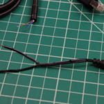
The important thing to remember is that the blue and brown wires are the power input to the lidar. As shown in the video, prepare the cable by cutting the control wires to a length of about 1/2″. The control wires are everything but the blue and brown wire. Bend the control wires over the existing heat shrink tubing and use some electrical tape to both insulate the wires and keep them in place.
Then cut the power wires to about 1″ in length. Strip off a 1/4″ of insulation. Twist each wire separately, and tin them with solder.
In the video, a 1.35mm x 3.5mm M/F 3′ Jack to Plug cable is cut in half. The plug side is cut to 6″, and about 1/4″ of insulation is removed. Twist each wire separately, and tin them with solder.

Add some heat shrink tubing to each of the plug wires, and slip a larger piece of shrink tubing over the Hokuyo side. The large piece of heat shrink should be enough to cover both the bent over wires and the actual connection itself.
Once the heat shrink tubing is in place, solder the plug wires to the Hokuyo power wires. A simple butt joint should be sufficient. In this example, remember that the blue wire is ground (-) and should go to the black wire from the plug. The brown wire is positive (+), and should go to the wire on the plug with the white stripe.
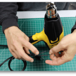
Heat Shrink
This is the best part! Heat shrink tubing is always fun!
Cover the power wires with the heat shrink tubing. Do the small heat shrink tubing first. Once the heat shrink tubing is in place, apply heat. The tubing will magically shrink to fit the wire.
Once the inner heat tubing is done, place the larger heat shrink tubing over the joint. Then apply heat. Here’s how the sequence should look:


Battery Connection
You will also need a cable to connect to the battery. If you are using an Energizer 18000 in the MIT RACECAR configuration make a Y cable. One cable comes from the battery ( you can use the “blue” wire from the Energizer kit). You will plug this cable into the 19V jack on the battery. The cable splits in to a Y. One side of the Y goes to the 1.35mm x 3.5mm jack wire from the previous step. The other side of the Y goes to the Jetson. The Jetson plug is 2.5mm ID, 5.5mm OD. I’ve found the right angle version helps remove some cable clutter.
Your wiring may vary, but make sure that the wiring of positive and ground across the 3.5mm jack and plug is consistent when wiring the Hokuyo.
We use two outputs on the Energizer. The 19V powers both the Jetson and the Hokuyo. The 12V output powers the ‘green’ cable, which connects with the USB hub. You may use the green cable in the Energizer kit, and splice it to a 1.7mm ID, 4.75mm OD plug connector. Again, right angle is a good choice here.
Before installing the Hokuyo in the robot, connect it to the battery to make sure that it is getting power.
RACECAR/J Installation
The Hokuyo generates quite a bit of heat during operation. Hokuyo recommends an aluminum plate to help with heat dissipation. The RACECAR/J store carries a LIDAR Aluminum Heat Sink for Hokuyo UST-10LX. If you remember in one of our previous articles RACECAR/J Platfrom Preparation we mount a Delrin plate to mount the lidar. In this application, substitute the aluminum version. Note: Full RACECAR/J kits contain the aluminum plate, there is no need to buy an additional one.
As shown in the video, attach the 1″ aluminum standoffs to the lidar plate using four 7/16″ 4-40 machine screws. Next, use two M3x10mm machine screws to attach the Hokuyo to the lidar plate. Once secured, attach the assembly to the lower platform deck using four 7/16″ 4-40 machine screws.
The cable management is more an art form than science at the moment. Use some zip ties to help route the wiring on the bottom side of the platform appropriately. You can watch the video to get some hints.
Once everything is assembled, ready for testing. Off to the testing article.
Note
The Energizer 18000 battery is currently in stock. However, over the last six months or so it has been difficult to get. Here are some other links and an alternative:
4 Responses
Is there any connector/adaptor I can buy so I do not need to cut the original wire? The original connector for the power line is SHR-06V-S.
I figured out a way to link the Hokuyo without cutting the original wire. I also connect the Hokuyo to the other lower voltage port of the battery so no need to use Y cable. I can post the details and Digikey part numbers if anyone is interested.
can u post it, i need to know
I set HOKUYO-UST-10LX Lider and try to connect internet by wifi, but couldn’t. Ethernet “ROS” which has IP:192.168.0.15 same as video. When I select Ethernet “ROS”, tele-operating and lider work by roslaunch racecar teleop.launch. But I cannot connect internet by wifi. On the contrary, wifi is on, roslaunch has error. Are there any setting for this error? I would like to tele-monitouring through second PC while tele-operating. Could you please advise me? I set TX2’s ROS_MASTER_URI:192.168.0.15:11311, ROS_IP:192.168.0.15 .