

In the sixth part of our Jetson RACECAR build, the upper platform is mounted to the lower platform and the initial test fitting commences. Looky here:
Background
As noted in Jetson RACECAR Part 5, there were issues mounting the PCA9685 PWM Driver, as the breakout board did have the correct sized mounting holes for the standoffs being used. In the video, a couple of alternatives were discussed to fix the issue (I left out using a hot glue gun, just because it was embarassing). One alternative was to place the PWM Driver on a larger circuit board and then mount the circuit board to the platform. Unfortunately the PWM Driver Board does not lend itself to easy placement in such a situation, so that idea was rejected. Of course, different sized standoffs could be used (which is the recommended way to go). However, this particular board has already been used in three other projects, so a chance was taken. Two of the mounting holes on the breakout board were drilled out to accommodate the mounting screws. There are all sorts of issues with this approach, not the least of which is ESD damage to the device, but since I have a couple of spares I figured it was worth a try.
Once the mounting holes were drilled out, the PCA9685 was test fitted on the lower platform.
Upper Platform Mounting
A 8 1/2″ x 16 1/2″ x 3/16″ sheet of impact resistant acrylic was used for the upper platform. Layout lines were drawn 1″ in from the sides of the sheet, and six mounting points were marked for the 2″ 4/40 female/female standoffs which are used to connect the lower platform with the upper platform. Two points were also marked as places to mount the antennas for the wireless NIC.
The lower and upper platforms were clamped together while 1/8″ holes for the standoffs were drilled through both pieces of acrylic. This helps to make sure that the two holes align on each platform. The platforms where then separated, and 1/4″ holes were drilled for the antenna mounts.
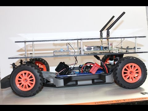
After the holes were drilled, the upper platform was test fitted. Everything seemed to go smoothly, the only issue being was that the top platform was off by a little from the center line of the car.
Note: A lot of the measurement and alignment issues have to do with hand cutting the acrylic sheets. Using a table saw or router table would be a preferred way to cut the sheet stock so that everything remains square. For the “real” version, the platform material (ABS) will be cut using either a CNC machine or laser cutter.
Next Up
This should be the core minimum to get the RACECAR ready to move under Jetson control. The next step is to build the ROS software needed to control the car, along with a tele-operation node so that the car can be controlled with a Bluetooth controller.
After installation of the upper platform, here’s what the Jetson RACECAR looks like:

