In the first article on the Jetson RACECAR project we described several tasks that need to be completed. The first task on the list that we’ve chosen to work on is building the Jetson RACECAR steering control. Looky here:
Background
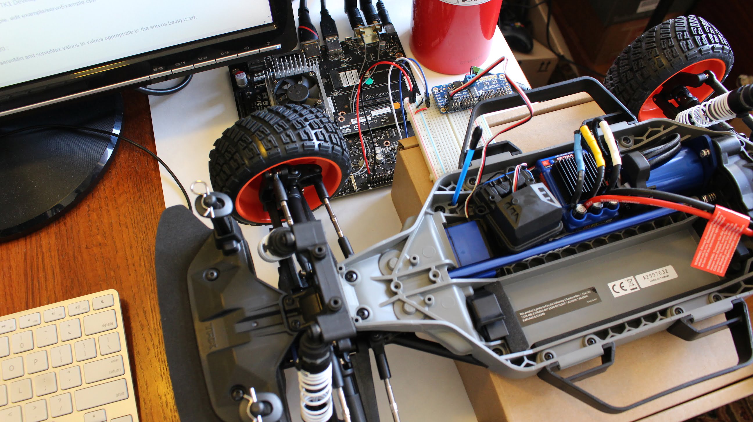
In previous articles such as this one, we discussed connecting a servo to a Jetson Development Kit with a PCA9685 Servo Driver. As you might recall, there is an associated repository on Github called JHPWMDriver. This code can be used on both the NVIDIA Jetson TX1 and Jetson TK1 Development Kits. The overall approach is to unplug the steering servo in the Traxxas RALLY from the receiver and plug it into a PCA9685 breakout board which in turn is connected to a Jetson via I2C.
There were two unknowns at the start. First, is the plug on the servo the same as the servo headers supported on the PCA9685? The second unknown is the voltage needed by the steering servo to operate. After removing the steering servo plug from the Traxxas RALLY receiver, it was measured and appeared to have the same IDC type of spacing (2.54mm) as other servos that we have used.
After charging the Traxxas battery, the transmitter was turned on, the battery connected to the car, the ESC powered on, and the voltage was measured as 6 volts on the steering servo header.
Knowing that the PCA9685 breakout board could physically support the servo pins and that through an optional connector the board could supply 6 volts to the servo from an external power supply, it was time to get started. It might just work!
Wiring
We have covered using I2C with the Jetson TX1 in an earlier article. In this demonstration, we used a Jetson TX1 with the same I2C pins wired as in the previous article; the Jetson TX1 J21 pins 27 (SDA) and 28 (SCL). These are I2C_GP1_DAT and I2C_GP1_CLK respectively, on I2C bus 1. The PCA9685 is wired from these signals, using the 3.3V supply from J21 Pin 1, and GND from J21 Pin 6. Note:The Jetson TK1 can also be used for this application, of course the wiring is a little different. See this article for more details.
The wiring is straightforward with 4 wires. The 3.3V from the Jetson goes to VCC on the PCA9685, GND from the Jetson goes to GND on the PCA9685. SDA from the Jetson goes to SDA on the PCA9685, the same with SCL.


Tools and Supplies
- Battery Charger (In the video, a SKYRC iMAX B6AC V2
 was used)
 - Multimeter (Optional, a Fluke 115 Electricians True RMS Multimeter was used)
- PCA9685 Breakout Board – Adafruit 16-Channel 12-bit PWM/Servo Driver – I2C interface – PCA9685

- Breadboard (In the video, a Solderless BreadBoard, 400 tie-points, 4 power rails was used)
- Power Jack Adapter (In the video, A female DC Power Jack 5.5mm x 2.1mm CCTV Power Jack Adapter was used).
- Power Adapter for Servo(s) (In the video, a 6V 1A AC Adapter To DC Power Adapter 5.5/2.1mm was used).

Software Setup and Installation
Once the board is wired up, power up the Jetson.
In order to be able inspect the PCA9685, you may find it useful to install the i2c tools:
$ sudo apt-get install libi2c-dev i2c-tools
After installation, in a Terminal execute:
$ sudo i2cdetect -y -r 1
You should see an entry of 0x40, which is the default address of the PCA9685. If you have soldered the address pins on the PCA9685 (as is the case if you are using multiple boards chained together) you should see the appropriate address.
JHPWMDriver Install
There is a PCA9685 driver available in the JHPWMDriver repository on the JetsonHacks Github account. To install:
$ git clone https://github.com/jetsonhacks/JHPWMDriver.git
$ cd JHPWMDriver
$ cd example
The example is specifically some other servos, but can be used as a guide. In the source file ‘servoExample.cpp’, uncomment the lines:
// int servoMin = 120 ;
// int servoMax = 720 ;
We’ll have to figure out what good values are for this as we start working on the steering code.
Save the file, and make the example:
$ make
To run the example:
$ sudo ./servoExample
The ‘sudo’ is required to gain permission for the I2C bus from user space.
At this point, all sorts of magic happens! Well, to manage expectations, the front wheels should turn from left stop to right stop. You’ll probably hear that the servo value min and max are off from the sound of a little servo whine at the steering stops.
Conclusion
Now that the Jetson can control the steering servo, with a little work we should be able to calculate the correct control settings. There’s some software to be written to control the steering servo from ROS as part of an Ackerman steering robot. Still, it’s nice to have cleared the first hurdle.
19 Responses
what is write byte error….
sorry i have a question .
is pca9685 working on TK1 board 32bit??
I did just following you. but it happened error when i write $sudo ./servoExample
The error is pca9685 write byte error.’pca9685 write byte error’ this sentence repeated infinite…
please solve my problem
sorry i have a question .
is pca9685 working on TK1 board 32bit??
I did just following you. but it happened error when i write $sudo ./servoExample
The error is pca9685 write byte error.’pca9685 write byte error’ this sentence repeated infinite…
please solve my problem
Do you see the 0x40 from
$ sudo i2cdetect -y -r 1
How did you wire the PCA9685 to the TK1? Did you try looking at:
https://jetsonhacks.com/2015/10/14/pwm-servo-driver-board-nvidia-jetson-tk1/
I wired corretly
And when i write sudo ./setTrottle, i can see 0x4vut after that sentence it happened error..
Could the pca9685 also be used for servo input to TX1, or is it only servo output?
(Say I have some RC car remote with a couple of servo channels, and want to connect it to TX1 directly to read its values.)
The PCA9685 is a PWM output device. To my knowledge, it cannot be used to read PWM pulses. For that application, you need a device which can read PWM pulses reliably with a ADC (Analog to Digital Converter) section. People typically use a microcontoller (such as an Arduino) for this task with a Jetson. An alternative might be something like: https://www.adafruit.com/product/1085
Will this work on a Jetson TX2?
It should work on a Jetson TX2, but you will have to change the library to match the GPIO addresses of the TX2. The Jetson TX1 GPIO addresses are different than the TX2. Thanks for reading!
Can you follow this guide using Jetson TX2?
I believe that it should work directly, but have not tested it personally. Thanks for reading!
I am doing ML inference in Python code, taking in images from the Jetson TX1 camera. Based on that, I want to control the servo. Should I use Python ctypes for that? Or is there a smarter way to do that?
It depends on what you’re trying to do. There are Python libraries available for the PCA9685 (such as from Adafruit) that should be easy to port to the Jetson, or you can write a ctype wrapper of some sort. Good luck on your project, and thanks for reading!
Hello,
can i please no which voltage the signal of the servo received. The Jetson Board has a SDA with just 3.3V output. I tried to control my servo but it doesn’t work. I use the microServo 9g.
Hello,
I am using the same way to connect the Adafruit board to the Jetson TX2, and when I run the servoExample, the address is 0x40 and it keeps repeating the PCA9865 Write Byte Error: 121, and when I run i2cdetect only the dotted lines show up. Could you point me in a direction what am I doing wrong? I have the SDA from the Adafruit connected to pin 3 on Jetson, SCL to pin 5, VCC is on pin 37 and GND on pin 34. Thanks in advance
If i2cdetect did not see the device, then you probably can’t write or read it. Note that the TX2 and the TX1 may use a different i2c bus. In other words, check with i2c if the device is on a different bus, e.g.
$ sudo i2cdetect -y -r 0
When I run on 0 bus, I get this:
0 1 2 3 4 5 6 7 8 9 a b c d e f
00: — — — — — — — — — — — — —
10: — — — — — — — — — — — — — — — —
20: — — — — — — — — — — — — — — — —
30: — — — — — — — — — — — — — — — —
40: UU UU UU UU — — — — — — — — — — — —
50: — — — — — — — — — — — — — — — —
60: — — — — — — — — — — — — — — — —
70: — — — — UU — — UU
And when I run sudo i2cdetect -l, this is what shows. Is the bus number 4 the PWM board or is it not showing at all?
i2c-0 i2c Tegra I2C adapter I2C adapter
i2c-1 i2c Tegra I2C adapter I2C adapter
i2c-2 i2c Tegra I2C adapter I2C adapter
i2c-3 i2c Tegra I2C adapter I2C adapter
i2c-4 i2c Tegra BPMP I2C adapter I2C adapter
i2c-5 i2c Tegra I2C adapter I2C adapter
i2c-6 i2c Tegra I2C adapter I2C adapter
i2c-7 i2c Tegra I2C adapter I2C adapter
i2c-8 i2c Tegra I2C adapter I2C adapter
Pin 37 is a GPIO, not a voltage source. For example, you can try pin 1 or 2 for VCC. Use Pins 3 and 5, you are using I2C Bus 1.
hello. After successfully running the test program, I am getting write byte error: 9 even though it worked perfectly before.